Срочная публикация научной статьи
+7 995 770 98 40
+7 995 202 54 42
info@journalpro.ru
Numerical evaluation of Friction Stir Welding (FSW) for 5086 aluminum alloys
Рубрика: Технические науки
Журнал: «Евразийский Научный Журнал №3 2016» (март)
Количество просмотров статьи: 3644
Показать PDF версию Numerical evaluation of Friction Stir Welding (FSW) for 5086 aluminum alloys
Mohammed Ali Abdulrehman (Materials Eng. Department, College of Engineering / Almustansiriya University, Iraq) Email: aljaraah_muhammad@yahoo.com
Abstract:
Aluminum alloys were welded with traditional welding techniques, such as Arc, TIG, MIG, etc….In recent years new technology had appeared called Friction Stir Welding (FSW). The focus of this research is the developing to a finite element simulation of FSW of 5086 aluminum alloy. Numerical simulations based on ANSYS-14.5 software are used for density, thermal conductivity and specific heat to find out the how these factors are related to peak temperature, also to find out the impact of heat distribution on the microstructure of 5086 aluminum alloy. Changing of temperature with input measurable factors is observed. The simulation model is verified with experimental results. The results of the simulation are in accordance with that of experimental results.
Keywords: friction stir welding (FSW), rotating speed, feed speed, specific heat.
1- Introduction
FSW is discovered by The Welding Institute of Cambridge, and it is a solid-state joining process. In the FSW process, a rotating tool containing a pin and a shoulder is connected to the joint between two specimens, producing heat by friction. Once the heat has reached up to the desired level, the tool is translated along the joint. Plasticized base material distributed around the tool, where it is consolidated due to force applied by the shoulder of the tool as shown in fig.(1) [1].
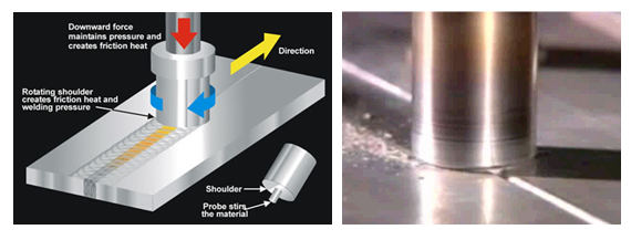
Fig. (1) Friction stir welding - procedure principle [2].
And the aim of work is Building numerical simulation with ANSYS program of temperature distribution for studied alloy and comparing with experimental results for verification.
2 Procedure of FSW
FSW was made on the 5086aluminum alloy plates with a thickness 3 mm, width 75 mm and length 200 mm as show in Fig. (2), a clamping fixture was used in order to the specimens were fixed to be welded on a MITSUBISHI CNC M70V milling machine fig.(3).
And the standard mechanical properties and chemical composition of 5086 AA of the present work and standard are shown in Table 1 and 2 respectively.
Table 1 Chemical Composition of 5086 AA [3]

Table 2 Mechanical properties of 5086 AA

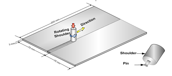
Fig. (2) Schematic of friction stir welding (FSW) for plates
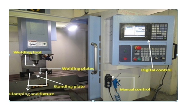
Fig. (3) MITSUBISHI CNC M70V milling machine
The initial FSW tool designed was a simple cylindrical tool with 16 mm shoulder diameter (SD) and 5 mm pin diameter (PD) [ as SD =( 3-3.5)PD [4] ], height of the pin equal to the distance that plunged in the plate and it was 2.9 mm of the sheets processed the length of the stirrer resembles as the required welding depth. The rotation of the stirrer operated the welding process at different rotational and welding speeds with a constant friction force as show in fig (4).
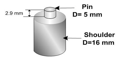
Fig. ( 4 ) FSW tool
Steel tool X40 was used to make the welding tool as shown in table 3.
Table 3 Show the Chemical Composition of welding tool

Table 4 FSW process at variable rotation speed at 60 mm/min feed speed
3- Thermal Modeling
The welding process is simulated by FSW modeling using finite element approach (ANSYS 14.5 program) to obtain temperature distribution on welded plate (sheets) at 1700 rpm and 60 mm/min and to calculate the heat input during welding process depending on assumed maximum temperature. Another objective of FSW modeling is to propose a method to calculate force required for welding process.
In order to facilitate the moving tool on the sheet welded line in program of ANSYS, all next steps (as shown in flowchart in fig. (5)) were made to make it like the tool moving along welded line in the program of ANSYS.
Fig. (5) Flowchart of thermal modeling
To get a good accurate of results, more steps of shoulder area must be made in the simulation of program as shown in Fig. (6).
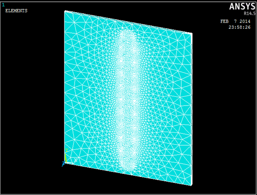
Fig. (6) Steps of circular shoulder area along welded line.
Where each shoulder circle has a specific time step and heat generation, each circle indicates one step.
For practice part has been measured temperatures for 5086 aluminum alloy using thermal Imaging camera shown in fig. (7).
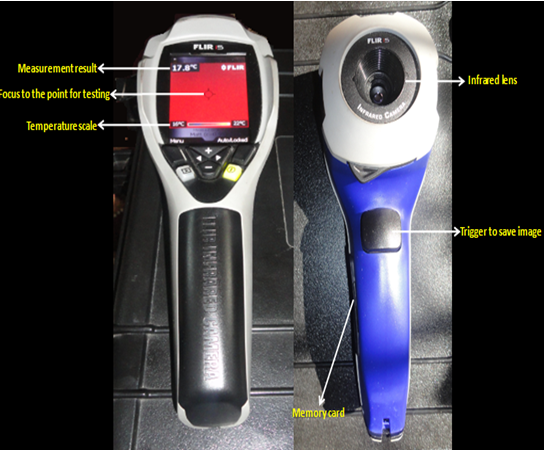
Fig. (7) Thermal imaging camera
And has been selected one point A (70 * 170) mm for testing in the same dimensions for alloy and the results of temperatures were recorded to the ram of thermal imaging camera to explain the relationship between temperature and time.
And in this test to clarify the comparison between the results of the practice results by thermal camera and the theoretical results by ANSYS program.
4- Results and Discussions
Experimental results for 5086 aluminum alloys are welding by FSW in this chapter. The most common measure of FSW quality after welding was done.
4.1- FSW Results
The friction stir welding (FSW) joints are shown in fig. (8).
Fig. (8) Welding beads upper surface of 5086 AA plates produced appearance by FSW
4.2 Results of numerical modeling of FSW
Experimental results of FSW of 5086 Aluminum alloys were compared with simulation results of ANSYS program at point A. The welded work piece had dimensions of (150 ×200 ×3) mm, shoulder radius of tool had a 8 mm, 3 mm pin radius and 2.9 mm pin length. The rotation speed and Feed speed that were utilized in this comparison were 1700 RPM and 60 mm /min for 5086.
440 seconds is the total time is required to complete the FSW for 5086 AA. Fig. (9) show how to exhibiting a certain results of the readings temperature for variable periods time for the same point of two welded alloys by thermal imaging camera.
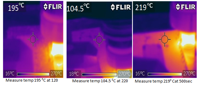
Fig. (9) some reading temperatures of FSP for 5086
Fig. (10) below show the results that are calculated experimentally and simulation results.
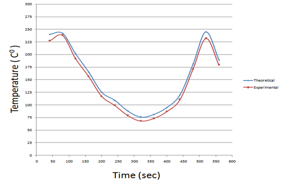
Fig. (10) Temperature distribution in point A for FSW of 5086
The modeling of this work is solved and the temperature distribution obtained for the model and the result show that there is very good agreement between present work and ANSYS result. But there is simple different in results with calculation temperature distribution between experimental examination and modeling ranging between 3 – 8 %.
Figure (11) to (13) show the maximum temperature of welding plate which has been reached at several time steps:
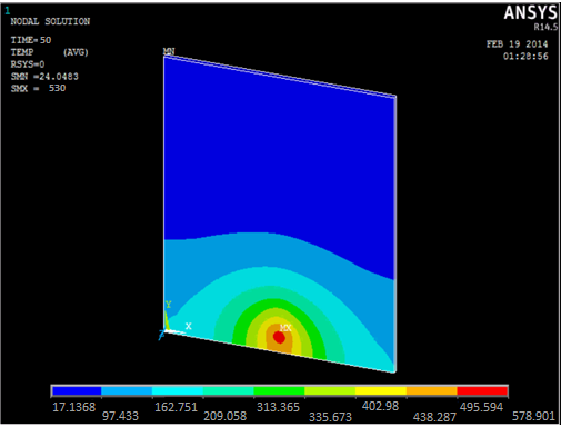
Fig. (11) Temperature distribution of 5086 AA plate at step 50second, maximum temperature is 530C 0.
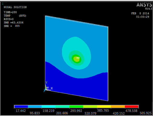
Fig. (12) Temperature distribution of5086 AA plate at step 288 second, maximum temperature is 455 C 0.
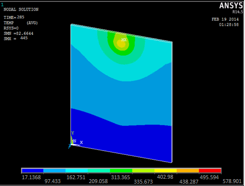
Fig. (13) Temperature distribution of 5086 AA plate at step 285 second, maximum temperature is 445 C 0.
From the fig. (11), fig. (12) and fig. (13) that the highest temperature for welded 5086 AA is 530 C0.
From this above the temperature of all crystals for welded two alloys reached to the recrystallization temperature ( Trec ) because of [ Trec = (0.5 – 0.8 ) [5]] , that with the FSW get in the recrystallization stage .
5- Conclusions:
Simulation of finite element model is more effective with enhancement capability to expect peak temperature during FSW of 5086 aluminum alloy and experimental results is validated with this model. A thermal model of three dimensional is developed for simulating the process of heat transfer for FSW using ANSYS 14.5 code. From the results, the following can be calculated:
-
Variation in the nugget-zone temperature with respect to time.
-
The temperature decreases with distance in perpendicular direction of the tool on the top surface.
-
Peak temperature variate with specific heat, thermal conductivity, and density obtained.
-
Comparison of experimental results and simulation values for the temperature profile to show the ability of more precise determination utilizing the present simulation.
References
- H.J. Powell, and K. Wiemer, Joining technology for high volume manufacturing of lightweight vehicle structures, TWI, Cambridge, 1996.
-
R. Itharaju, friction stir processing of aluminum alloys, University of Kentucky, MA, 2004.
-
R. Nandan, T. DebRoy and H. K. D. H. Bhadeshia, Recent Advances in Friction Stir Welding – Process, Weldment Structure and Properties, Materials Science 53, 2008.
-
The Aluminum Association, Standards and Data, 2005.
-
ASM International, Vol.2 - Properties and Selection: Nonferrous Alloys and Special-Purpose Materials, Metals Handbook, 10th Ed, 1990.

